在测试半导体器件的功能之前,通常需要验证器件的结构完整性,包括从测试件到被测器件的连接。直流参数测量单元(PMU),用于通过强制(force)电压/测量(measure)电流(FVMI)以及强制电流/测量电压(FIMV)对器件进行直流特性测试。同样的,PMU可用于验证UUT和tester之间的连接的完整性。
本文重点介绍如何使用GX5295的每引脚PMU功能在被测器件上执行连续性测试(Continuity test)和短路/开路测试(continuity and shorts / opens tests)。测试程序是用ATEasy编写的,也可以使用任何主流编程语言。下面所以截图都是基于ATEasy应用程序。这里描述的测试可以在从半导体IC到印刷电路板的各种device上进行,因此ATEasy应用程序可以被很容易地移植到其他器件的测试中。

图1.Marvin Test Solutions GX5295 -PXI digitial I/O&PMU
本文的重点也是测试的第一步,是要确定被测器件(DUT,Device Under Test)是否与tester完好连接 - 在这个例子中tester是GX5295数字IO (DIO)。该测试称为“Continuity”测试,它通过检测IC引脚上的ESD二极管(IC里面会有ESD保护电路的设计)来验证tester和DUT之间的连续性。tester到DUT的连续性是通过将小电流施加到DUT引脚,并测量是否存在电压来测量的。这利用了GX5295的PMU的强制电流,测量电压(FIMV)能力。
ESD保护二极管是一个半导体器件,正常情况下当电流流过时,它产生的电压应与半导体结(junction)上的压降一致。如果ESD二极管不存在,或者在Continuity测试时如果tester未连接到DUT引脚,电流将不会流过ESD二极管,并且电压将与半导体结压降不一致。如果ESD二极管发生故障,则可以检测出其他异常的电压,例如在二极管被短路的情况下,ESD二极管上测量的电压为“0”伏。(这是后面的测试中的理论基础)
Pin Mapping
在进行任何测试或测量之前,您必须定义系统配置。创建了一个ATEasy “Command”,这个命令允许测试程序员定义安装在测试夹具中的DUT(被测设备)的数量及其引脚数。有关在ATEasy中定义命令的其他信息,请参阅ATEasy Help/Commands在线文档。假设所有的DUT都是同一种器件。通过下面这个命令指定要测试的DUT器件数量(nCount),每个DUT(nPins)的引脚数:
Dut Define Counts(nCount, nPins)
为了在DUT引脚上加电流/测量电压,有必要在软件中定义tester resources和DUT IO之间的连接。在本示例中,使用ATEasy中定义的另一个特殊命令执行引脚映射,该命令将在结构化阵列中存储“Tester-Channel to DUT-Pin”相关性。引脚映射结构还保留DUT引脚名称和引脚类型(输出,输入,IO,Vcc1:4和Ground) - 这对于提供有关被测试引脚的信息非常有用。使用时,“Dut Define PinMap”命令指定DUT pin_type,DUT pin_name,DUT pin_number以及包含DIO通道号channel_number的数组。channel_number[]用于索引DIO通道号,以支持从多个DUT的引脚映射到对应的DIO通道。命令的形式如下:
Dut Define PinMap pin_type ("pin_name",pin_number, channel_number[])
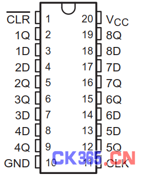
以Texas Instruments 20针TSSOP封装的SN74HC273八通道锁存器为例。

图2.Texas Instruments SN74HC273 -TSSOP封装
用于定义DUT器件数量,DUT引脚数和DUT / DIO引脚映射的命令如下所示。
注意:为了清楚起见,DIO通道阵列被定义为与引脚映射命令一致,但是可以通过诸如从文件或电子表格读取或通过从专用GUI输入通道号等方式来输入:
Dut Define Counts(1,20)
Dut.DioChannels={0}
Dut Define PinMap Input ("Clr-", 1, Dut.DioChannels)
Dut.DioChannels={1}
Dut Define PinMap Output ("Q1" , 2, Dut.DioChannels)
Dut.DioChannels={2}
Dut Define PinMap Input ("D1" , 3, Dut.DioChannels)
Dut.DioChannels={7}
Dut Define PinMap Input ("D2" , 4, Dut.DioChannels)
Dut.DioChannels={4}
Dut Define PinMap Output ("Q2" , 5, Dut.DioChannels)
Dut.DioChannels={5}
Dut Define PinMap Output ("Q3" , 6, Dut.DioChannels)
Dut.DioChannels={6}
Dut Define PinMap Input ("D3" , 7, Dut.DioChannels)
Dut.DioChannels={3}
Dut Define PinMap Input ("D4" , 8, Dut.DioChannels)
Dut.DioChannels={8}
Dut Define PinMap Output ("Q4" , 9, Dut.DioChannels)
Dut.DioChannels={-1}
Dut Define PinMap Ground ("Gnd" ,10, Dut.DioChannels)
Dut.DioChannels={17}
Dut Define PinMap Input ("Clk+",11, Dut.DioChannels)
Dut.DioChannels={15}
Dut Define PinMap Output ("Q5" ,12, Dut.DioChannels)
Dut.DioChannels={10}
Dut Define PinMap Input ("D5" ,13, Dut.DioChannels)
Dut.DioChannels={13}
Dut Define PinMap Input ("D6" ,14,Dut.DioChannels)
Dut.DioChannels={12}
Dut Define PinMap Output ("Q6" ,15, Dut.DioChannels)
Dut.DioChannels={11}
Dut Define PinMap Output ("Q7" ,16, Dut.DioChannels)
Dut.DioChannels={14}
Dut Define PinMap Input ("D7" ,17,Dut.DioChannels)
Dut.DioChannels={9}
Dut Define PinMap Input ("D8" ,18,Dut.DioChannels)
Dut.DioChannels={16}
Dut Define PinMap Output ("Q8" ,19, Dut.DioChannels)
Dut.DioChannels={1000}
Dut Define PinMap Vcc1 ("Vcc" ,20, Dut.DioChannels)
注意:需要提一下两个特殊的引脚映射参数。首先,为DUT “Gnd”信号指定的“-1”DIO通道表示该DUT引脚未映射到任何DIO通道。在这种情况下,这是由于DUT负载板的布局,其将DUT Gnd引脚连接到接地层而不是DIO通道。其次,为DUT“+ 5V”Vcc引脚指定DIO通道“1000”表示Vcc引脚连接到GX5295上的四个辅助IO引脚(Aux)之一。这些“Aux”通道从1000开始映射到DIO通道。将DIO通道1000指定为DUT Vcc输入意味着GX5295 AUX 0通道将为DUT提供Vcc电压。
Continuity Measurement
为了进行continuity test ,已经定义了另一个ATEasy命令。该命令接受DUT number和DUT pin。 DUT pin是个变量(Variant),可以接受由DUT映射命令定义的DUT名称,DUT pin作为文本参数,或DUT pin number作为一个数字参数。通过引用(指针)传递另外两个参数,并返回与DUT pin变量相关联的DUT pin number和DUT pin name。该命令在施加小负载电流至引脚后返回该引脚的一个Double类型的电压测量值。命令的形式如下:
dMeasurement = Dut PMU Measure Continuity (nDutNumber,varDutPin, pnDutPin, psDutPin)
作为面向对象的编程语言,ATEasy为其Task/Test结构中定义的每个测试提供唯一的名称(请参阅ATEasy Help/Test)。测试名称可以使用“Test”对象变量和“Name”属性在运行时以文本字符串的形式访问,如下所示:
string = Test.Name
通过简单地使用Test.Name调用Dut PMU Measure Continuity()命令,并将Test.Name定义为DUT pin name或DUT pin number来大大简化整个测试程序。下面的示例通过定义the test name来测量DUT引脚的连续性,并使用ATEasy的内部定义的TestResult变量来存储连续性测量值。对于每个测试,连续性测量都可以被以一样的方式调用:
TestResult=Dut PMU Measure Continuity (1, Test.Name,pnDutPin, psDutPin)
ATEasy Task/Test结构的一个例子如下图所示。请注意,每个测试名称是唯一的,与上面的引脚映射命令中使用的名称相同。还要注意,每个测试提供了用于判定continuity test的Pass/Fail状态的最小和最大电压值(最小/最大参数在高亮显示的命令上方可见)。ATEasy将根据Min / Max参数自动评估返回到TestResult的测量值,以确定每个continuity test的Pass/Fail状态,并将自动将评估结果的报告传递给测试日志Test Log(standard output)或ATEasy Test Executive(ATEasy测试管理驱动)。

图3.Continuity Task/Test Structure and Test Command
Test PMU Measure Command 附加到进行continuity测量的procedure中被调用。在这个procedure中, TestContinuity位于名为DUT的驱动程序中,本文中讨论的命令也是这样。这个procedure调用另一个这个procedure,_GetPinInfo 在结构数组中搜索通过命令传递的DUT Variant pin的name或number,当搜索到时,提取与该引脚相关联的DUT pin number和DIO channel number。 _GetPinInfo的代码如下所示:
Procedure _GetPinInfo(nDutNumber,varDutPin, nDioPin, pnDutPin, psDutPin): Void
--------------------------------------------------------------------------------
nDutNumber: ValShort !DUT devicenumber
varDutPin: Val Variant !DUT Pin("Name", "Number" or valNumber)
nDioPin: VarShort !DIO Channel number
pnDutPin: VarShort !ReturnedDUT pin number
psDutPin: VarString !ReturnedDUT pin name
nHandle: Short !DIO handle
iPin:Long !Pin index counter
{
! Get the DIO session handle
Dio Get MasterHandle(nHandle)
If VarType(varDutPin)=vtBstr
! The procedure searches the structure array for the"name"
! or "number" of the DUT pin passed in by thecommand,...
For iPin=0 to m_nDutCount[1]-1
! and when"name" is found...
IfLCase(m_astDomain[nDutNumber-1,iPin].Name)=LCase(varDutPin)
! theDUT pin number is saved, ...
pnDutPin=iPin+1
! theDUT pin name is saved, ...
psDutPin=m_astDomain[nDutNumber-1,iPin].Name
! theDIO channel number is used for the measurement process
nDioPin=m_astDomain[nDutNumber-1,iPin].DIO
ExitLoop! exit the loop
! or when "number"is found...
ElseIfVal(varDutPin)=(iPin+1)
! theDUT pin number is saved, ...
pnDutPin=iPin+1
! theDUT pin name is saved, ...
psDutPin=m_astDomain[nDutNumber-1,iPin].Name
! theDIO channel number is used for the measurement process
nDioPin=m_astDomain[nDutNumber-1,iPin].DIO
ExitLoop! exit the loop
EndIf
Next
! If the DUT pin "name/number"was not found...
If iPin=m_nDutCount[1]
! generate an error exceptionand return
Error 1,"DUT pinname/number ""+varDutPin+"" not found"
Return
EndIf
Else
pnDutPin=varDutPin
! If the DUT pin number exceeds it'slimits...
If pnDutPin<1 orpnDutPin>m_nDutCount[1]
! generate an error exceptionand return
Error 1,"DUT pin number"+Str(pnDutPin)+" invalid"
Return
EndIf
! The DUT pin name is saved, and ...
psDutPin=m_astDomain[nDutNumber-1,pnDutPin-1].Name
! the DIO channel number is used for themeasurement process
nDioPin=m_astDomain[nDutNumber-1,pnDutPin-1].DIO
EndIf
}
_GetPinInfo返回的DIO channel number用于continuity测量。 DIO channel置于Force Current模式中,+ 5V和-2V的整流电压(电压钳位)施加到DIO通道,以将DUT引脚电压保持在DUT的安全级别。对DIO通道施加小的负电流(-0.5mA),并测量所得到的电压。测量完成后,DIO通道返回动态(dynamic)模式(默认),测量电压返回到正在被调用命令中。完整的ATEasy算法如下所示:
Procedure TestContinuity(nDutNumber,varDutPin, pnDutPin, psDutPin): Double
--------------------------------------------------------------------------------
nDutNumber: ValShort !DUT devicenumber
varDutPin: Val Variant !DUT Pin("Name", "Number" or valNumber)
pnDutPin: Var Short !ReturnedDUT pin number
psDutPin: VarString !ReturnedDUT pin name
nDioPin:Short !DIO Channel number
dContinuity:Double !Continuityvoltage measurement
nHandle:Short !DIO handle
{
! Get the DIO session handle
Dio Get MasterHandle(nHandle)
_GetPinInfo(nDutNumber,varDutPin,nDioPin,pnDutPin,psDutPin)
! The DIO channel is placed in the Force Current mode and...
Dio Setup Channels Mode PmuForceCurrentModeRangeOfChannels(nHandle,nDioPin,nDioPin)
! commutating voltages (voltage clamps) of +5V and -2V are defined
Dio Setup Channels PMU ForcedCurrentCommutatingVoltageRangeOfChannels(nHandle,nDioPin,nDioPin,5.0,-2.0)
! A small negative current (-0.5mA) is applied to the DIO channel, and...
Dio Setup Channels PMU ForceCurrentRangeOfChannels(nHandle,nDioPin,nDioPin,-0.5,aPmuCurrentRange_n2ma_to_p2ma)
! the resulting voltage is measured
Dio Measure PmuVoltage(nHandle,nDioPin,dContinuity,250)
! The DIO channel is returned to dynamic (default) mode and...
Dio Setup Channels Mode DynamicIo RangeOfChannels(nHandle,nDioPin,nDioPin)
! the measured voltage is returned to the calling command
Return dContinuity
}
Results
ATEasy将根据Min / Max参数自动评估返回到TestResult的测量值,以确定每个continuity test的Pass/Fail状态,并将自动将评估结果的报告传递给测试日志Test Log(standard output)或ATEasy Test Executive(ATEasy测试管理驱动)。图4显示了测试执行器输出,引脚2的DUT开路故障,以及引脚9的DUT短路故障。(这两种故障被称为continuity故障)
结合图5二极管的伏安特性曲线可分析:引脚2的测量值为-1.8220V已经远超二极管反向击穿电压值,所以是开路故障,在status一列被标记为“Fail”;引脚9的测量值为+0.0020V表现为非常小的正电压值,所以是短路故障,在status一列被标记为“Fail”,这两个电压测量值都超出了Min (-0.85V)/ Max(-0.5V)参数范围。

图4.ATEasy Test Executive Output with DUT continuity Failures

图5.二极管的伏安特性曲线


